I have completed the rewire project on my ’66 Tiger 1A and have a few comments and photos which I would like to share. I hope this article can be of benefit to any member planning the same project. The photos like I’ve taken would have been a great help to me in considering my options and establishing a direction. There’s not much of anything I wish I had done differently on this project. Everything worked when it was hooked up according to the wire labels and I didn’t cut any wires too short, or at least I haven’t realized it yet. I have many more photos that I won’t bother to post unless someone has a specific question that one of them might clarify.
I used the Rebel Wire kit from
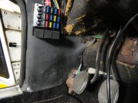
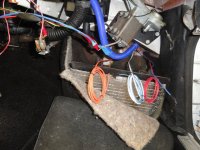
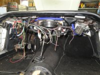
www.petesperformancewiring.com which has twelve fused circuits and three relays. A big plus is that it was designed for my car and all wires are labeled every six inches. I chose to put the fuse panel up high on the kick panel of the driver’s side. It is obviously larger than the OE two fuse panel out on top of the fender well and I thought it would crowd that area too much. I used fully insulated connectors similar to the OE because a partially bare connector at the fuel pump is what prompted this whole rewiring event. Photos 12-08-21 (19) and 12-08-28 (21) show the end result toward which I was working.
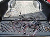
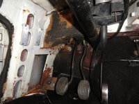
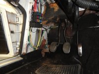
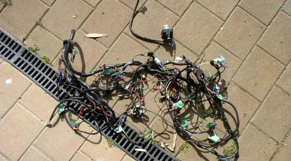
Photo 12-08-13 (3) shows what happens if you short your fuel pump to ground with the OE harness----a sad day indeed! If you are in an old English car and you think the guy in front of you is emitting smells of something burning, STOP!!! It might be you!!! I had pretty much completed assembling a basket case which included a new wiring harness and was beginning to drive the car around, looking for that “warm fuzzy feeling” of confidence that I now had a reliable driver. The wire split open from the fuel pump to the junction at the fuse box, from there to the ignition switch, and then to the starter solenoid.
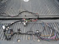
Photo 12-08-13 (4) shows my burnt harness taken apart to salvage the good wires that connect from switch to switch. These wires would have had to be made up with connectors on both ends anyway. As I had mentioned, my harness was new before this happened, so I kept the benefit of having the good insulated connectors and the wire colors per the OE Tiger wiring diagram. None of these were damaged by the meltdown.
Photo 12-08-14 (2) shows the mounting I created for the fuse panel assembly. It is made from .25” x 1” aluminum rails mounted on .5” diameter X .5” long nylon spacers. This gave me the .75” clearance for the wire bulge on the underside of the fuse panel. The two rails are tapped #10-32 and match the pattern on the fuse panel assembly. Both are identical. All of this material can be found @ Lowe’s or Home Depot.
Per the instructions, I began wiring the lights first to get them out of the way. Photo 12-08-16 (3) shows where I ran all of the wires that weren’t connected to any switches in the dash to the engine compartment. These would be the front lights as well as engine control wires, all for the right side of the car. I put them in the wire conduit to keep it neat and it would also help the job appear less intimidating. Please note that the high quality SXL wire has a sticky feel and doesn’t slide particularly well when bundled, so avoid placing the wire in the conduit twisted, just in case you need to pull one wire further through or back in the other direction. They would have taken up less space to wrap them with tape, but if I need to pull one out or add a wire in the future, it would be messy. Just a note: all switch wires run from switch-to-switch, switch-to-apparatus, or toward the fuse panel.
Photo 12-08-20 (2) shows where I put the wires I didn’t use, (Electric Choke, Radio, Oil Pressure Gauge, Generator Light, and Accessory). Most are hot, coming from the fuse panel, and so I taped the ends before I rolled them up and dropped them behind the false floor for possible future use. Some are plenty long. The Accessory wire is probably 8’-10’ long. Note that if it is one that is not connected on either end, then it can be pulled either direction. This is true only if it is in the conduit and not wrapped with tape as mentioned earlier.
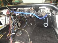
Photo 12-08-21 (6) shows the panel mounted, with left front light wires through the firewall and tail light, fuel gauge, and FUEL PUMP wires headed down and toward the rear. Notice the short ground wire for the relays. My car had an OE ¼-28 tapped hole there, (near my upper left mounting hole), which I conveniently used. I’m not sure what it was intended for, possibly a speaker mount, but it didn’t appear to have ever been used.
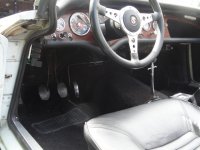
Photo 12-08-21 (15) shows were I had all of the switches working before I began putting the dash board back in place. The loose wires are for the gauges and panel lights. I cut them to length and added the connectors as the gauges went in.
I found it to be very practical to install the dashboard without anything attached except the heater controls. I used those empty gauge holes to hook up the heater control cables and to access the wiring to tidy things up; creating maximum space to access the back of the gauges later.
Additional Notes:
This kit comes with the brake light wire split off for a third brake light. I plan to shop for one and am looking for ideas that exclude drilling any holes.
I ran my cooling fan signal wire to the accessory terminal on my ignition switch, so in an overheating situation I can switch off the engine and still have cooling in process. My cooling fan power supply wire has its own fuse and connects directly to my Ford 3G one wire alternator terminal.
I powered my tach and voltmeter off of the input side of the voltage stabilizer. It has an extra tab and the supply is fused.
The daisy chain instrument lights and ground wires don’t come with the kit, so you’ll have to use your old ones. Hope yours are good enough to use in a new and improved setup.
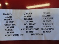
Photo 12-08-16 (01) is the layout of the fuse panel supplied with the kit. Column on the right contains fuses for everything that has power all the time. The four circuits in the middle only have power during “ignition switch on.”
The four on the left are powered during both “ignition switch on” and “accessory switch on.”
As far as I can see, the only unfused wires are those that supply current to and from the ignition switch.
I hope this has been a big help to some and anyone reading this article has my permission to use any information herein as you wish.